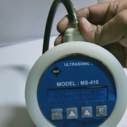
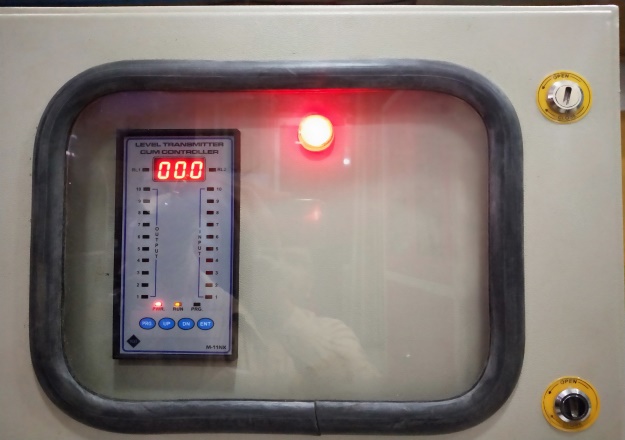
Ultrasonic Top Roller Lift Transmitter Model MS-410
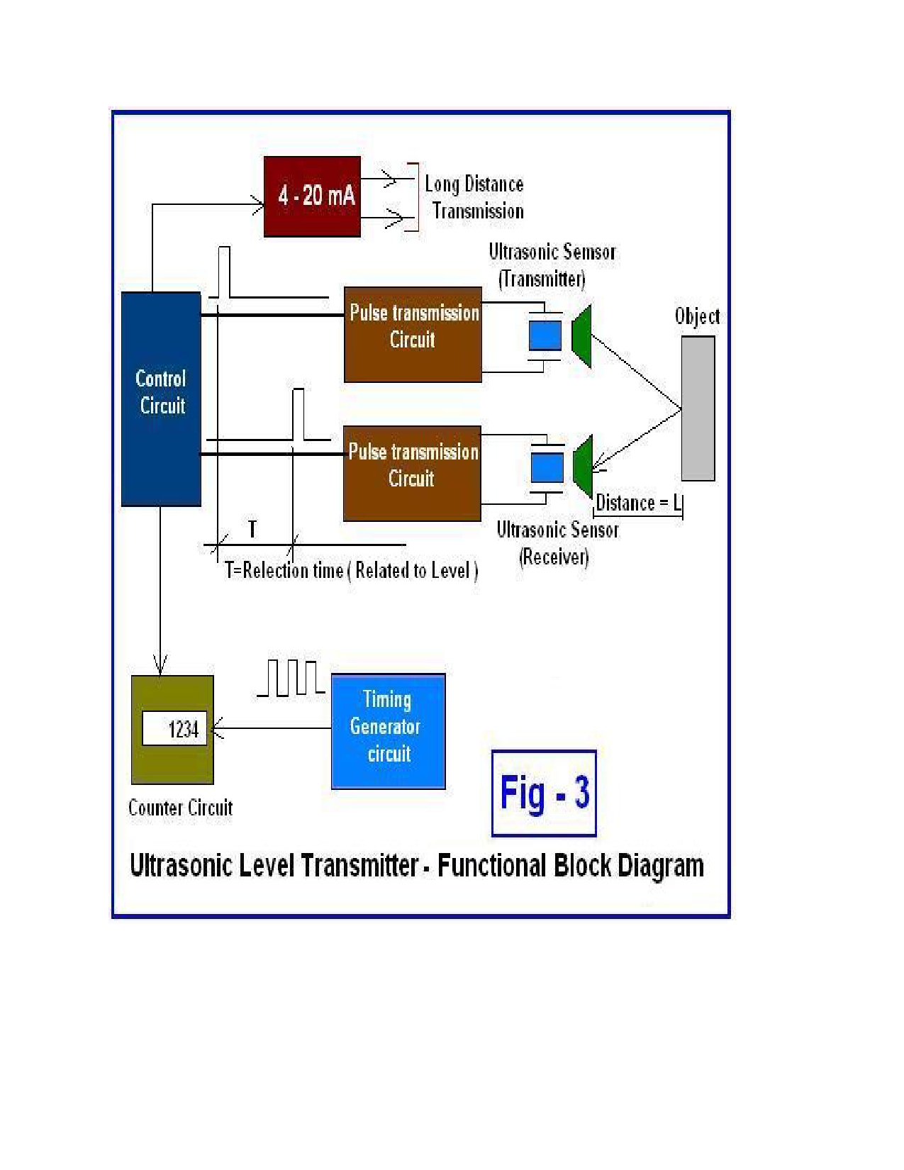
This is microprocessor based Ultra-sonic Level Transmitter. It has Multifunction Instruments It is capable of monitoring Virtually Any Short Or Medium Range of Non-Contact Ultrasonic Level Measurements of Liquids, Solids Or Slurries. In this Instrument User can take measurements of Roller Lift of mills, water level and select the range in the range parameter and set Reverse action in Action parameter. It has One Analog Output 4-20mA and two digital control output (we can also define these two digital control output as relay 1and 2).
(Click to download Operation Manual PDF)
(Click to download Catalog version 2 PDF)
Top Roller List Indicator Transmitter
Latest and modern technology based Mill Top Roller Lift Measurement through Ultrasonic type sensor and solid state digital indication systems specially design for measurement and display of Mill Top Roller Lift. Ultrasonic Sensors shall be Top Mounted on Mill Top Roller and Digital indicators are designed for Panel mounting in industry environment. The digital indicator indicates the instantaneous value of Roller Lift (0-50mm) is to be measured through Ultrasonic type Sensors and Transmitters. Please read the instructions carefully before installing the system.
Installation
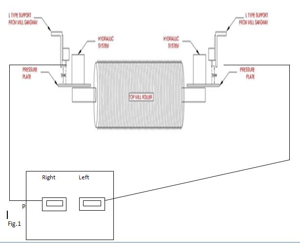
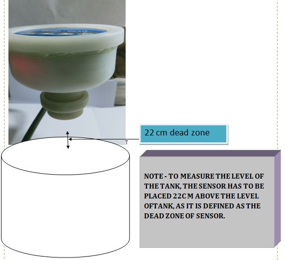
A rod will be welded at the pressure plate of top roller and at the top of this rod a square 4”×4” MS plate will be welded at rod’s Centre, Then we will insert and fit a Ltype support arrangement with ultrasonic transmitter and then the system will be placed 270 mm above the square plate.( the sensor tip of transmitter should be 270 mm above the Centre of plate) because 22cm is the dead zone of transmitter. Show in fig1.
Configuration
The range parameter of ultrasonic transmitter should be set as 50 mm And the action parameter should be set as 1 value.
Note: To measure the level t of the tank, the sensor has to be placed 22cm above the level as it is defined as the dead zone of the sensor.
Specifications
Measuring Range: 0-5 Meters
Main (auxiliary supply) : 24V DC
O/P (Analog) : 4-20mA
Digital (RL1&2) : +24v common
Display LCD : 16 x2
Display value : In CM And MM(Millimeter)
Reverse Action : User can be take 4-20mA in revers action
Wire’s colure code
Power supply : +24v Red Wire
: -24v Black Wire
Analog o/p (4-20mA) : + mA White Wire
: – mA Green Wire
Digital o/p : +24v common Brown Wire
: Digital o/p1 Blue Wire
: Digital o/p2 Yellow Wire
ACTION PARAMETER – if we mention the value of action parameter as 1 then it will work in reverse order and if value is mentioned as 0 it will work in forward order.
RANGE PARAMETER – in range parameter we have to define that value which gives the output of 420mA.
Working
REVERSE ACTION
if we mention the value of action parameter as 1 , suppose the object is placed 1 m (value of range parameter ) from the transmitter then this value will be considered zero and as the object will move closer to it ,it will begin to sense the distance and will give the output as soon as when the object will be at 22cm it will display maximum range i.e 420 mA.
FORWARD ACTION
if we mention the value of action parameter as 0 and the object is placed closer to the transmitter ie22cm from it or less than that ,it will consider it as zero and show dead zone and at this time the range will be 3.8 mA .when the object will move farther from 22cm it will sense the value and display the output.