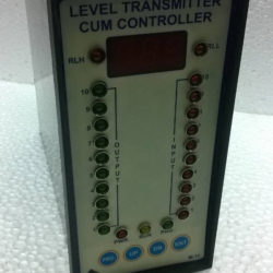
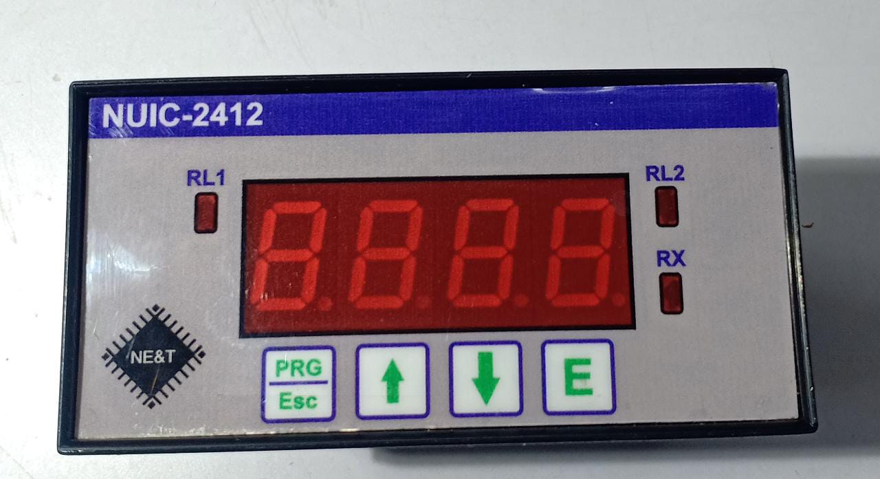
Process Indicator Controller cum Transmitter, Model NUIC-2412
Introduction
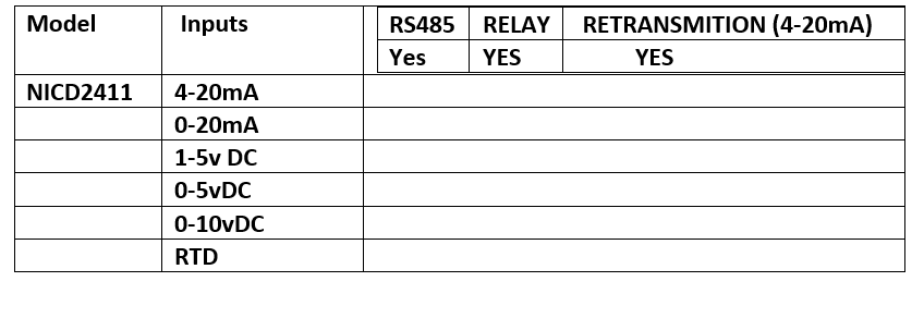
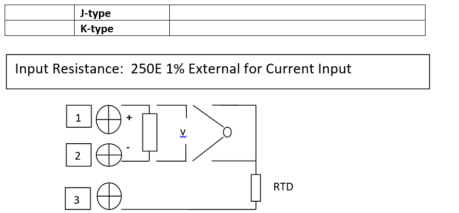
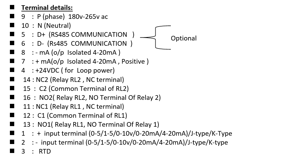
This is micro-controller based Process Indicator Controller Cum Process Transmitter. The instrument has universal inputs like 0-20mA/4-20mA/0-5vDC/1-5VDC/0-10VDc/RTD/J-type/K-type and it also has retransmission output 4-20mA and Modbus (RS485) Communication, and 2 Relay control.
Operation
- Before connecting power supply insure that you are connecting I/P voltage to the right terminals. On application of proper power supply & input sensor. The instrument will display Control / Set Point value in lower display and Process Value in upper display.
- Key Operation
- By pressing PRG key, For Configuration mode.
- By pressing UP /DN key value can be change and press Ent key for store modified value.
- Relay Operation
- Relay : Relay OFF when value is less than Set value & ON when value is more than Set value and Vice-versa.
Specifications
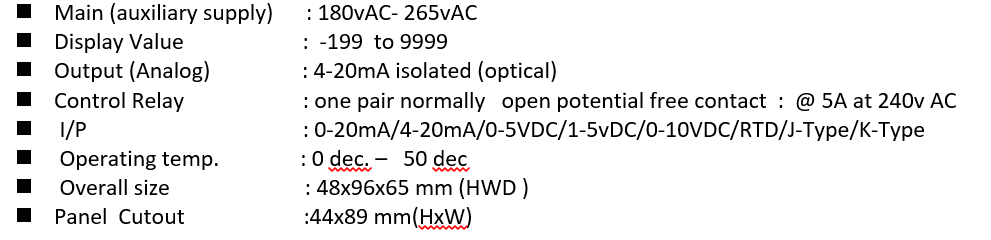
Parameters

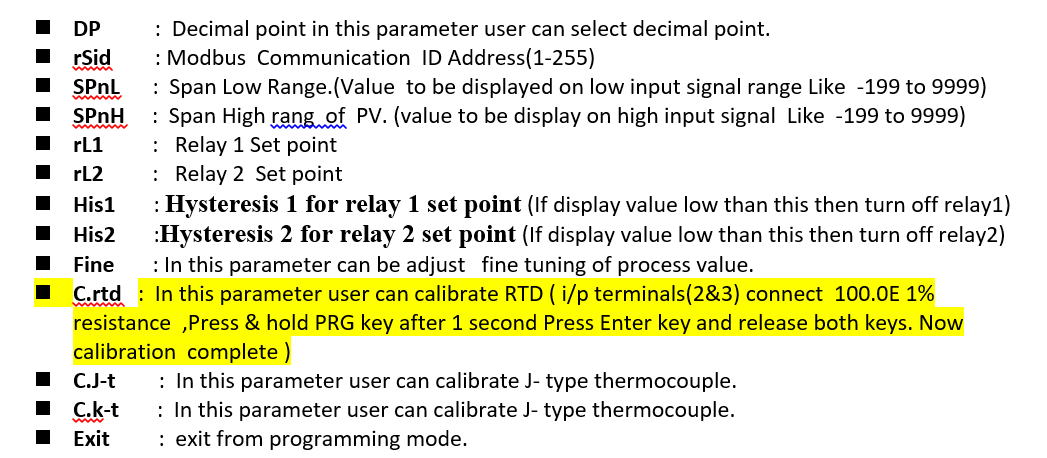
How can you calibrate thermocouple J/K
Apply MV at terminal +1 & -2 , Press PRG key for 3seconds Now display input parameter here use upkey/dnkey and select C.J-t/C.K-t parameter press enter key, display present value of thermocouple if need adjustment then use up/dn key set right value(according the temp. chart) and subtract ambient temperature value from it , now Press and hold PRGkey after 1second press Ekey and release both keys. Now Calibration Completed.
How can calibrate RTD(PT100)
Apply 100.0E 1% Resistance at terminal 2 & 3 ,Press PRG key for 3seconds Now display input parameter here use upkey/dnkey and select C.rtd parameter press enter key, display present value of the resistance if not show 100.0 E then Press and hold PRGkey after 1second press Ekey and release both keys. Now Calibration Completed.
How Can select Parameters
1st Press Prgkey for 3 seconds display inputs parameter in this parameter user can select any one input and press Ekey for next parameters use upkey and pervious parameter use dnkey . User can select any parameter by use upkey/dnkey . ‘Exit Parameter’ in this parameter if press E key then exit from programming mode.
Communication
PROTOCOL : Modbus RTU serial
STANDARD : RS-485
BOUDA RATE : 9600 BPS
DATA BIT : 8 BITS
STOP BIT : 1
PARTY : NONE
MODBUS ID ADDRESS : 1-255
The unit can be connected in RS-485 communication data link either in multi drop or repeat mode. Each unit must have unique Serial Number. Entire range of addresses (1 to 255) may be used. Before starting any communication, choose a baud rate compatible to the host computer. The serial protocol used is MODBUS RTU.
Read Holding registers FUNCTION = 03
Master Query: [ id] [Function Code][High Addr. Byte][Low addr. Byte][No of Points
High][No. of point low][CRCL][CRCH
Slave Response: [ id] [Function Code][ Byte Count.][Data High][Data Low ] [CRCL][CRCH]
Master Query:
[ id] ]Function Code][High Addr. Byte][Low addr. Byte][No of Points High][No. of point
low][CRCL][CRCH]
SN. ADDRESS PARAMETER NAME
1. 4000 PROCESS VALUE (R)
2 4001 Load value (0-1000) for retransmission
CALIBRATION
Press and hold Dnkey + Prgkey for 5 seconds then display “Zero” now apply 0mA at input terminal(+1 &-2) after that press E key now display ADC value counts wait for 3 seconds then press and hold Prgkey after 1 seconds press Ekey and now release both key ,Display CALL (Low calibration) now apply 4mA at input terminal (+1 & -2) after that press Ekey Now display ADC counts wait for 5 seconds then Press and hold Prgkey after 1 seconds press E key and now release both keys, Display CALH(High Calibration) now apply 20mA at input terminal(+1 & -2) after that press E key now Display ADC counts wait for 5 seconds then press and hold Prgkey after 1 seconds press E key Now calibration complete . Note after calibration parameter SPANL/SPANH must be redefine.
Note: 250E 1% resistance must be connect at terminal 1& 2 at the time of calibration
Faults/Errors
1. Err1:
2. -Err:
3. Open:
4. Undr
5. over
Err1: If the instrument is showing error1, then the internal data of the instrument has been corrupted in this error, now it has to be defaulted. The default value to be loaded in internal memory through for the following process. 1st switch power of the instrument power after press & hold Dnkey + Upkey +Ekey then power switch on of the instrument after 10 seconds releases both key, Now instrument must be reconfigure and recalibrate .
-Err: If the instrument is showing -Err, it means input terminal connection is reversed. So please change input terminal connection (+1 / -2).
Open: input terminal wire disconnected or input source has been faulted.
Undr : input value low then 4mA/1VDC.
Over : input higher than defined range setting.