PID Controller Model No. NICD2411
Introduction
This is micro-controller based PID Controller Cum Process Controller. The instrument has three modes one is PID mode 2nd is re-transmission mode 3rd is Manual mode. User can select any one, suppose user select 2nd mode (Re-transmission mode) In this mode user can take 4-20mA output according the input. In the 3rd mode user can take 4-20mA by use key pad (manually) .The
upper display show process value and lower display show output value/Set point. The Instrument has Modbus (RS485) Communication And 2 Relay control.
User Manual (Click to download): PID Controller Model No. NICD2411
Thank you for purchasing PID/Process Indicator Controller NICD2411. This manual describes the basic functions and operation methods of NICD2411. Please read through this user’s manual carefully before using the product.
Operation
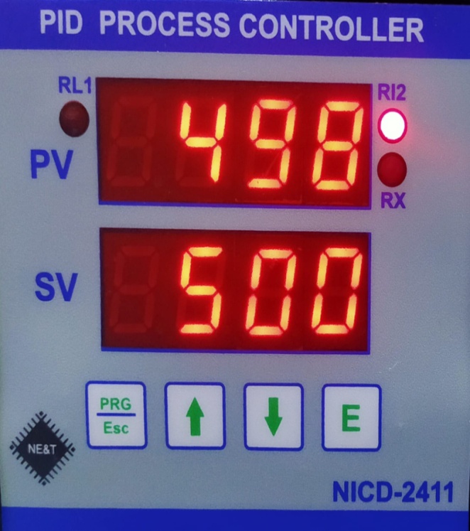
Before connecting power supply insure that you are connecting I/P voltage to the right terminals. On application of proper power supply & input sensor. The instrument will display Control / Set Point value in lower display and Process Value in upper display.
Key Operation
- By pressing PRG key , For Configuration mode
- By pressing UP /DN key value can be change and press Ent key for store modified value
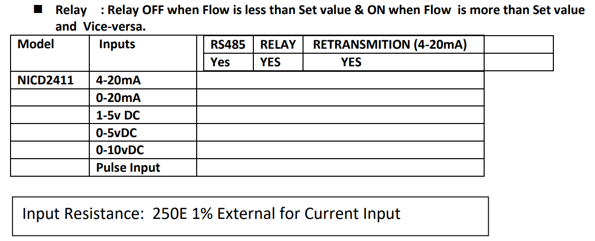
Relay Operation
Terminal Details
Terminal details:
1 : P (phase) 220VAC @50HZ
2 : N (Neutral)
3 : E (Earth)
15 : D+ (RS485 COMMUNICATION )
16 : D- (Rs485 COMMUNICATION )
17 : – mA (o/p Isolated 4-20mA )
18 : + mA(o/p Isolated 4-20mA , Positive )
13 : +24VDC ( for Loop power)
12: – 24VDC (for Loop Power)
14 : pulse input ( For K factor flow )
9 : NC2 (Relay RL2 , NC terminal)
7 : C2 (Common Terminal of RL2)
8 : NO2( Relay RL2, NO Terminal Of Relay 2)
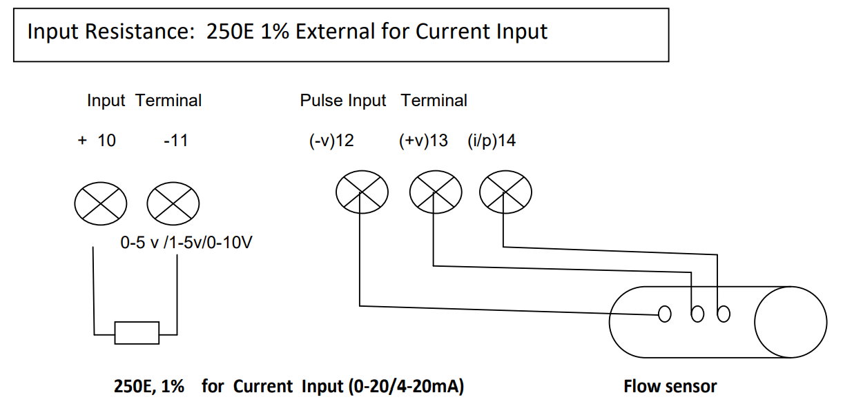
Input Resistance: 250E 1% External for Current Input
6 : NC1 (Relay RL1 , NC terminal)
4 : C1 (Common Terminal of RL1)
5 : NO1( Relay RL1, NO Terminal Of Relay 1)
10: + input terminal (0-5/1-5/0-10v/0-20mA/4-20mA)
11: – input terminal (0-5/1-5/0-10v/0-20mA/4-20mA)
Specification
- Main (auxiliary supply) : 220vAC @50Hz / 24 VDC/15V DC
- PV Display value : -199 to 9999
- SV Display Value : -199 to 9999
- Output (Analog): 4-20mA isolated (optical)
- Control Relay : one pair normally open potential free contact : @ 5A at 240v AC
- I/P : 0-20mA/4-20mA/0-5VDC/1-5vDC/0-10VDC/Frequency
- Operating temp. : 0 dec. – 50 dec
- Overall size : 96x96x65 mm (HWD )
- Panel Cutout :92×92 mm(WxH)
Parameters
- Inpt : in this parameter user can select type of input
- Actn : In this parameter user can select action Forward/reveres (For PID/Process Indication)
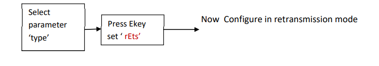
- Type : In this parameter user can select instrument Mode(PID/retrains./manual )
- DP : Decimal point in this parameter user can select decimal point.
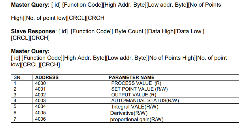
- rSid : Modbus Communication ID Address(1-255)
- SPnL : Span Low Range.(Value to be displayed on low input signal range Like -199 to 9999)
- SPnH : Span High rang of PV. (value to be display on high input signal Like -199 to 9999)
- diSP : in this parameter ,the user can select whether to show the Set point value in the SV
- display or to show the control output value .(SEtP=set point, outP= output value ,CmSP= comm.
set point etc) - rL1 : Relay 1 Set point
- rL2 : Relay 2 Set point
- His1 : Hysteresis 1 for relay 1 set point (If display value low than this then turn off relay1)
- His2 :Hysteresis 2 for relay 2 set point (If display value low than this then turn off relay2)
- SP– : in this parameter user can set value of PID set point.
- dEtd : In this parameter user can set Derivative value of PID Control(0-3000).
- Intr : in this parameter user can set integral value of PID Control (0-3000).
- Pd– : In this parameter user can set Proportional value of PID Control(0-999.0)
- dbnd : In this parameter user can set dead band % value of Set point( dead band= set point x
dbnd%) - Pdly : In this parameter user can set value of PID sample delay time(1= 1MS ).
- Fine : In this parameter can be adjust fine tuning of process value .
- Factor : In this parameter user can adjust K factor
- Exit : exit from programming mode.
How Can select Parameters
1st Press Prgkey for 3 seconds display inpts parameter in this parameter user can select any one input and press Ekey for nextparameters use upkey and pervious parameter use dnkey . User can select any parameter by use upkey/dnkey . Exit Parameter, in this parameter if press E key then exit from programming mode.
PID Control Mode
- In this mode use following parameters:
1.Type = PID
2. pdly = Pid delay time (1 value = 1MS)
3. Action parameter use for PID action forward/Revere mode
4. SP– = PID set point.
5. dEtd = Derivative value of PID Control action slow /fast(0-3000).
6. Intr : integral value of PID Control (0-3000).
7. Pd– : Proportional gain value of PID Set point(0-999.0)
8. dbnd : dead band % value of Set point( dead band= set point x dbnd%)
For fast action of PID control: then increase integral value & decrease derivative value and
adjust the value of proportional gain. For slow action of PID Control: adjust (increase ) derivative value & decrease integral value
and adjust proportional gain & derivative value
dbnd :
In this parameter the percentage higher and lower side of the set point is defined so that when the PID reaches the process value around the set point, the dead band comes into action at that time and which is the value of the dead band if the process value is within
that limit. So there will be no action on the control. And if the process value is more than the dead band value then the PID controls action will take place otherwise no action will be taken due to being in dead band.
SP–: In the running mode, if user press upkey + Prgkey then display set point press Ekey and set desired value by use up/dnkey and press Ekey
Auto/Manual Mode
First hold down the enter key and then press the prg key after which the instrument will automatically go into manual / auto mode. If earlier it is in AUTO mode then it will go in manual mode and if in manual mood then it will go in AUTO mode.
By pressing and releasing the enter key, the user can check whether the instrument is in auto mode or manual mode.Display: in the display parameter, the user can define whether he want to show the set point value on the SV display or show the PID control value. If select outP then display pid control output or if select SEtP then display PID set point value.
Process Indicator cum Controller(Mode2): In this mode user can be use the instrument as a process indicator / controller and take 4-20mA retransmission output .
K-Factor
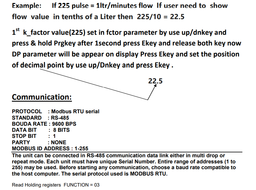
This K-factor will be given in terms of the number of pulses produced by the sensor/meter for a given volumetric flow. (e.g) 150
pulses per liter etc. This K-factor is the value that is entered into a batch meter or indicator/totalizer in order to give readout in engineering units.
Example 1
Example 1 : If the display on a flow rate meter is required in U.S. gallons per second, and the K-factor of the flow meter is 210 pulses
per U.S. gallon, then the K-factor entered into the rate meter would be 210. If a totalizer associated with the same flow meter was to be
set up so as to flow rate in U.S. gallons the indicator K-factor would be 210. If the indicator was to be set to flow rate in tenths of a
gallon the K-factor would be 210 /10 = 21, 21=K-factor Note: If user need to flow value in tenths of a gallon/Liter then
value of K factor = 21 set in factor parameter and k_decimal point set zero. If user needs to show flow value in ones then 210 value set
in factor parameter and k_decimal =0 .
Note for K-Factor
Note-For K-factor : Press Prg key display input parameter press E key and select puls input by up( )/dn( )keys after selection press Ekey now again display inpt now use up key for select for next parameter Fctr(kfactor) press Ekey now display last loaded value of k_factor,If you want change value then use up/Dnkey according your k_factor value (Like 225/22.5) now press & hold Prgkey after 1 seconds press E key now release both keys then display dP(Decimal Point) Press Ekey set decimal point according your k_factor value and Press Ekey now again display Fctr (it means K-factor value has been store)
Calibration
Press and hold Dnkey + Prgkey for 5 seconds then display “Zero” now apply 0mA at input terminal(+10 &-11) after that press E key now display ADC value counts wait for 3 seconds then press and hold Prgkey after 1 seconds press Ekey and now release both key ,Display CALL (Low calibration) now apply 4mA at input terminal (+10 & -11) after that press Ekey Now display ADC counts wait for 5
seconds then Press and hold Prgkey after 1 seconds press E key and now release both keys, Display CALH(High Calibration) now apply 20mA at input terminal(+10 & -11) after that press E key now Display ADC counts wait for 5 seconds then press and hold Prgkey
after 1 seconds press E key Now calibration complete . Note after calibration parameter SPANL/SPANH must be redefine
Faults & Errors
Faults/Errors:
1. Err1:
2. -Err:
3. Open:
4. Undr
5. over
Err1: If the instrument is showing error1, then the internal data of the instrument has been corrupted in this error, now it has to be defaulted. The defaultvalue to be loaded in internal memory through for the following process. 1st switch power of the instrument power after press & hold Dnkey + Upkey then power switch on of the instrument after 10 seconds releases both key, Now instrument must be reconfigure and recalibrate .
-Err: If the instrument is showing -Err, it means input terminal connection is reversed. So please change input terminal connection (+10 / -11).
Open: input terminal wire disconnected or input source has been faulted.
Undr : input value low then 4mA/1VDC.
Over : input higher than defined range setting.