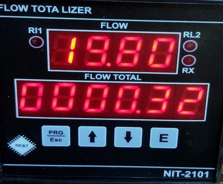
Flow Indicator Totalizer Model NIT2101
This is micro-controller based Flow Indicator Totalizer with Modbus (RS485) Communication And 4-20mA (Isolated) Re-transmission output & 2 Relay control . The manual covers all aspects of operation of the instrument. Please read instructions carefully before operating it. Foreword Thank you for purchasing FLOW INDICATOR TOTALISER NIT 2101. This manual describes the basic functions and operation methods of NIT2101. Please read through this user’s manual carefully before using the product.
Click here to download User Manual
Operation
Before connecting power supply insure that you are connecting I/P voltage to the right
terminals. On application of proper power supply & input sensor. The instrument will
display Totalizer value in lower display and actual Flow in upper display.
Key Operation
- By pressing PRG key, For Configuration mode.
- By pressing UP /DN key value can be change and press Ent key for store modified
value.
Relay operation
Relay :Relay OFF when Flow is less than Set value & ON when Flow is more than Set value
and Vice-versa.
Terminal details
- 1 : P (phase) 220VAC @50HZ
- 2 : N (Neutral)
- 3 : E (Earth)
- 15 : D+ (RS485 COMMUNICATION )
- 16 : D- (Rs485 COMMUNICATION )
- 17 : – mA (o/p Isolated 4-20mA )
- 18 : + mA(o/p Isolated 4-20mA , Positive )
- 13 : +24VDC ( for Loop power)
- 12: – 24VDC (for Loop Power)
- 14 : pulse input ( For K factor flow )
- 9 : NC2 (Relay RL2 , NC terminal)
- 7 : C2 (Common Terminal of RL2)
- 8 : NO2( Relay RL2, NO Terminal Of Relay 2)
- 6 : NC1 (Relay RL1 , NC terminal)
- 4 : C1 (Common Terminal of RL1)
- 5 : NO1( Relay RL1, NO Terminal Of Relay 1)
- 10: + input terminal (0-5/1-5/0-10v/0-20mA/4-20mA)
- 11: – input terminal (0-5/1-5/0-10v/0-20mA/4-20mA)
Specifications
- Main (auxiliary supply) : 220vAC @50Hz / 24 VDC/15V DC
- Max Flow Rate : 0000-9999
- Totalizer ; 6 Digit (000000-999999)
- Output (Analog): 4-20mA isolated (optical)
- Control Relay : one pair normally open potential free contact : @ 5A at 240v AC
- I/P : 0-20mA/4-20mA/0-5VDC/1-5vDC/0-10VDC/Frequency
- Operating temp. : 0 dec. – 50 dec
- Overall size : 96x96x65 mm (HWD )
- Panel Cutout :92×92 mm(WxH)
Parameters
- Inpt : in this parameter user can select type of input
- Hrs/mint : In this parameter user can select totalizer value in mints/hrs.
- Type : In this parameter user can select Linear/ Square Root
- DP : Decimal point in this parameter user can select decimal point.
- rSid : Modbus Communication ID Address(1-255)
- SPnL : Span Low Range.
- SPnH : Span High rang of flow
- rL1 : Relay 1 Set point
- rL2 : Relay 2 Set point
- His1 : Hysteresis 1 for relay 1 set point
- His2 :Hysteresis 2 for relay2 set point
- Fine : In this parameter can be adjust fine tuning of flow rate
- Factor : In this parameter user can adjust K factor
- rESt : In this parameter user can reset totalizer value .(password : 1234)
- Exit : exit from programming mode.
How to select parameters
1st Press Prgkey display inpt parameter in this parameter user can select any one input and press Ekey for next parameters use upkey( ) . User can select any parameter by use upkey . Exit Parameter, in this parameter if press E key then exit from programming mode.
Reset Totalizer
In parameter user can reset totalizer value. Press E key display 0000 value now set value 1234 and press enter key.
K-factor
This K-factor will be given in terms of the number of pulses produced by the meter for a given volumetric flow. (e.g.) 150 pulses per liter etc. This K-factor is the value that is entered into a batch meter or indicator/totalizer in order to give readout in engineering units.
Example 1 : If the display on a rate meter is required in U.S. gallons per second, and the K-factor of the flow meter is 210 pulses per U.S. gallon, then the K-factor entered into the rate meter would be 210. If a totalizer associated with the same flow meter was to be set up so as to totalize in U.S. gallons the totalizer K-factor would be 210. If the totalizer was to be set to totalize in tenths of a gallon the K-factor would be 210 = 210
Note: If user need to totalize in tenths of a gallon/Liter then value of K factor = 210 set in factor parameter. If user needs to totalize value in ones then 210 x10 = 2100 value set in factor parameter.
*Note for K-factor
Press Prg key display input parameter press E key and select puls input by up( )/dn( )keys after selection press Ekey now display inpt now use up key for select next parameter Hrs/Mint press E key and use up/dn key for select minutes and press E key Display Hrs/min parameter now use up key for next parameter FCtr(kfactor) press E key now set your k-factor value (Like 210/2100) now press & hold prg key after 1 seconds press E key now release both keys.
Communication
PROTOCOL : Modbus RTU serial
STANDARD : RS-485
BOUDA RATE : 9600 BPS
DATA BIT : 8 BITS
STOP BIT : 1
PARTY : NONE
MODBUS ID ADDRESS : 1-255
The unit can be connected in RS-485 communication data link either in multi drop or repeat mode. Each unit must have unique Serial Number. Entire range of addresses (1 to 255) may be used. Before starting any communication, choose a baud rate compatible to the host computer. The serial protocol used is MODBUS RTU.
Read Holding registers FUNCTION = 03
Master Query: [ id] [Function Code][High Addr. Byte][Low addr. Byte][No of Points
High][No. of point low][CRCL][CRCH
Slave Response: [ id] [Function Code][ Byte Count.][Data High][Data Low ] [CRCL][CRCH]
[ id] ]Function Code][High Addr. Byte][Low addr. Byte][No of Points High][No. of point
low][CRCL][CRCH]
*xxxxxxxxxxxxxxxxxxxxxxxxxxxxxxxxxxxxxxxxxxxxxxxxxxxxxxxxxxxxxxxxxxxx*
CALIBRATION: Press and hold Dnkey + Prg key for 5 seconds then display CALL (Low calibration) now apply 4mA at input terminal (+10 & -11) after that press E key Now display ADC counts wait for 5 seconds then Press and hold Prg key after 1 seconds press E key and now release both keys, Display CALH(High Calibration) now apply 20mA at input terminal(+10 & -11) after that press E key now Display ADC counts wait for 5 seconds then press and hold Prgkey after 1 seconds press E key Now calibration complete . Note after calibration parameter SPANL/SPANH must be redefine.
*xxxxxxxxxxxxxxxxxxxxxxxxxxxxxxxxxxxxxxxxxxxxxxxxxxxxxxxxxxxxxxxxxxxx*
Faults/Errors
- Err1:
- nErr:
- Open:
- Undr
- over
Err1: If the instrument is showing error1, then the internal data of the instrument has been corrupted in this error, now it has to be defaulted. Power of the
Default load in internal memory:
instrument after press & hold dn key + up key then power on of the instrument after 10 seconds releases both key now reconfigure and recalibrate of the instrument.
nErr: If the instrument is showing nErr, it means input terminal connection is reversed. So please change input terminal connection(+10 / -11).
Open: input terminal wire disconnected or input source has been faulted.
Undr : input value low then 4mA.