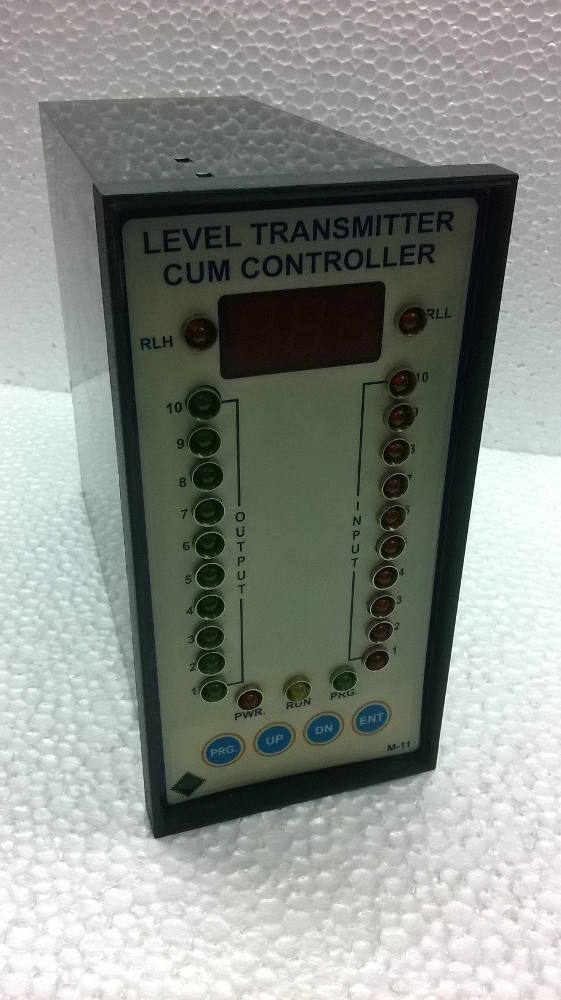
Donnelly Chute level Transmitter
This is micro-processor based Donnelly Chute level Transmitter with isolated o/p (4-20 mA), 10nos digital optical o/p and 2 relay control .The instrument is field programmable and user friendly.
In this Instrument user can set sensor sensitivity, sensor level selection, sample delay time and relay set point etc. The user can set level 2-10 then instrument automatically tunes for o/p 4-20 mA and display 0-100%.
The instrument has five settable parameters like rL1,rL2,snt,trl,Lst. The Instrument reads input level in sequence 1 to 10 if misplaced any level then it will not show above levels.
Operations Manual – Donnelly Chute Level Transmitter with Modbus Communication Model M11 NX
Operations Manual – Donnelly Chute Level Transmitter with Modbus Communication Model M11 MAX
Parameters
Snt: Sensor Sensitivity adjustment
Lst: Level Sensor selection (2-10)
Trl: sample Delay adjustment
RL1 and rL2 : Relay set point (0-100)
snt(sensitivity adjustment Parameter)
In this parameter user can set sensitivity of every (1-10 sensor) level sensor through key pad. The sensor value can be set in this parameter 93(Max.) to (185min.) sensitivity and it is normally set 100 value of every sensor.
If snt set 93 then i/p led direct on without input connection.
Lst(level selection parameter)
The user can be set input level 2-10 then instrument automatically tune for o/p 4-20 mA and display 0-100%
Trl = 20 set
rL1,rL2 : Relay set point value
Terminal Details
S1 to S10 : i/p for probe type level sensor
GND : Common terminal of probe sensor (Donnelly chute sensor)
L1 to L10 :o/p for isolated digital out put to plc
+24vdc : +v common (+24 vdc) for plc digital i/p
O/p 4-20 mA : mA output (isolated)
P : common terminal of Relay
N/O : Normaly open terminal of Relay
N/C : Normaly close terminal of relay
L : Phase of 220v AC @50/60Hz
N : Neutral
E : Earth
Specifications
Main (auxiliary supply) : 220vAc +-15% @50 Hz
O/P (Analog) : isolated 4-20mA
O/p (digital : isolated digital output (L1 to L10)
Relay set value : 000-100 settable
Display range : 0-100% according select sensor level (2-10) settable
Time delay setting : 001-100 ms settable
Input :10nos. Probe sensor (digital i/p)
Digital i/p / o/p : Indicate by LED as fitted on the front panel
LED : Red Led for i/p, Green Led optical digital o/p
Control Relay : one pair normally open potential free contact: @ 5A at 240v AC
Overall size : 96x194x223 mm (WxHxD )
Panel cutout : 184X92mm(HxW)
Configuration
1st press both PRG+ DN key for 5 seconds then display rL1 press ENT key
display last load value if change then Use up/dn key and press ENT key
display rL2 press ENT key display last load value if change then use up/dn key And press ENT key
display snt press ENT display 001(it means level 1 select to adjust sensitivity) press ENT
display last load value of sensor 1 sensitivity , if you want change value then use up/dn if value decrees (it means sensitivity higher side(93 max.) ) if value increase (it means sensitivity lower side(185 min.) if you want to store modified value then press and hold PRG key after press ENT key now release both key now modified value has been stored .
If you do not want to change in this parameter then use only ENT key, if press only ENT key it means by pass snt parameter, if press PRG key and ENT key it means modified value stored and display snt for next level sensor sensitivity calibration And same process apply for level 1 to level 10 after that, Next parameter Lst display press ENT key display last level select if change (2-10) then use up/dn key press ENT key display trL press ENT key display last value and set 20 and press ENT key and now exit configuration mode.
Wait for Run led on (Run led on it means ,system in run mode.)
Troubleshooting
1. Fault 01 : If Display Eror1
2. Fault 03 : if Display 100% value on fnd display
3. Fault 02 : if Display Eror2
Fault 01: if Display Eror1 message it means wrong level select, now re-select level in Lst
Parameter (2-10)
Fault 02: if system display Eror2 message it means stored data has be corrupted now switch off of power and press and hold up and ENT key now switch on of power and hold up to counting display 1 to 9 now release Both key.
Fault 03 : If 100% value On Fnd display and all input led(red colored) glow without input level connection, it means sensitivity low than 100 value, now go to calibration process & select snt parameter and set 100 value of every sensor.
Note: If snt parameter set93 then i/p led direct on without input connection.