
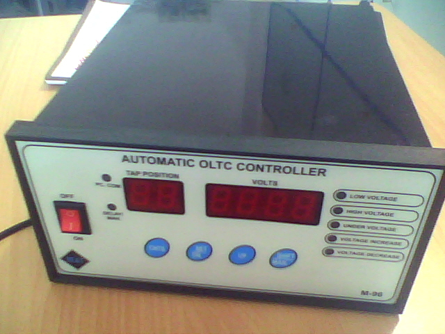
Automatic Voltage Regulating Relay Model M 96/350 T
Introduction
The Micro-Controller Based Automatic Voltage Regulating Relay Model M96/350T is used for regulating the secondary voltage of Power Transformer with on load tap changer. The required dead band settings are set by low voltage & high voltage parameters. The time delay setting is set by delay parameter. The delay parameter use for momentary fluctuations of the regulated voltage. The reducing the number of operations of the tap changer.
When the regulated voltage falls below the under voltage limit, the control relays are automatically blocked i.e. there is no voltage correction & under voltage relay is open contact positions.
Click here to download Operations Manual: RTCC Instruction Manual NE&T
Features
- 2 Digit display : For Tap Position
- 4 Digit display : For PT Voltage
- Readable 5 digit tap position change counter
- Under voltage Message display
- Over voltage message display
- 2 Relay contact 5 Amp. 240V provided for Voltage increase & Decrees.
- 1 Relay contact( normally close) provided for under voltage.
- D type 9 pin female connector provided for computer interfacing.
General Description
The dead-band (band width) can be set by setting low Voltage & High Voltage limits in parameter 1 (P1) parameter2 (P2). The desired time delay can be set in delay parameter (P3)
Operation of the voltage increase relay is automatically inhibited when the voltage falls below the specified under voltage limit or if PT fail.
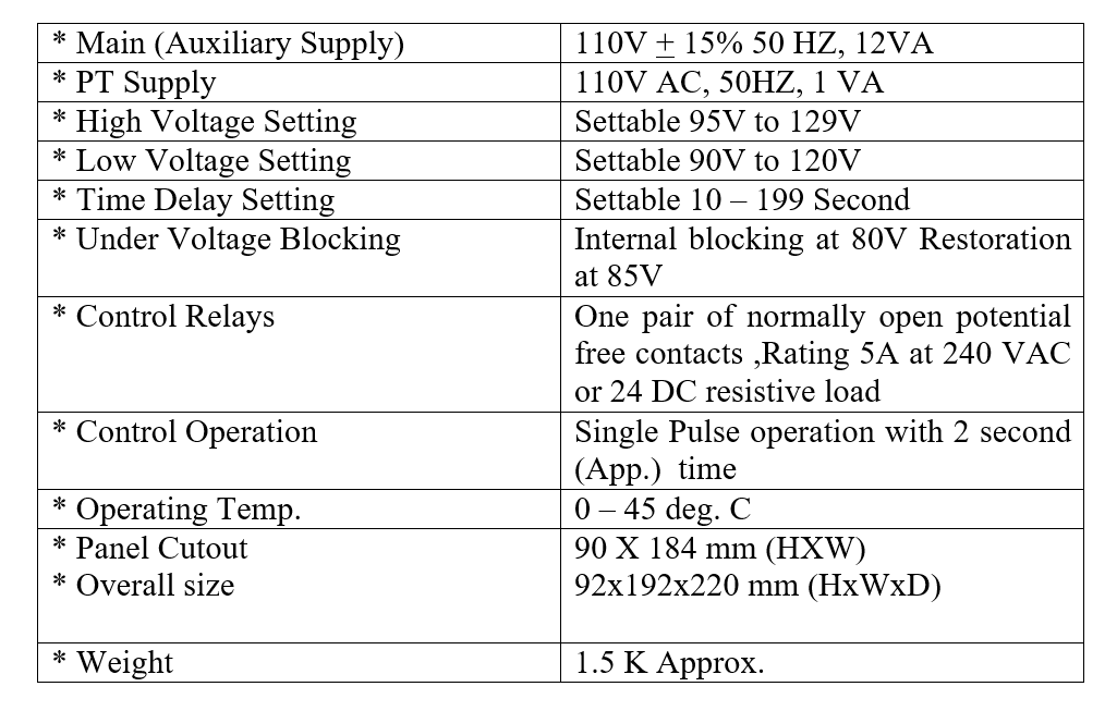
Specifications
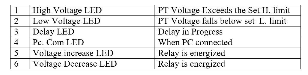
Indication
Controls
- Power-on : This is Rocker switch when “on” supplies Auxiliary voltage (Main)
Operating Instructions
- Check the PT Auxiliary (Main) fuse connect the PT & Auxiliary supply to the appropriate terminals (PT I/P) and mains of the rear panel terminal block. In case separate main supply is not available, then the same PT supply can be connected both PT & mains terminals. Leave the unit ON for 5 minutes before making any new sitting.
- Dead Band Settings : Set the High Voltage and low voltage setting the setting are made through the front panel touch dome switches,
- Under Voltage Blocking: This is factory set at 80V, Note that between blocking and the release (Restoration) a hysterics 5V has been provided.
- Time Delay: Time is a variable content with variation from 10 to 199 Sec.
Programming Parameters
Parameter(P2)
In this parameter user can be set low voltage Limit .(90-120v)
Parameter (P1)
In this parameter user can be set high voltage Limit (95-129v)
Parameter (P3)
In this parameter user can be set Delay time (10-199seconds)
Parameter (P4)
In this parameter user can be set over voltage range limit.
Not use in this instrument.
Parameter (Tap)
In this parameter user can be calibrate tap position
Calibration
Select tap parameter and press setkey display 0000
Now actual tap position feed on display by use up key(0-9)/shift(digit select) key and press and hold cntkey then press set key for 1 seconds after release both key now tap calibration complete.
AC voltage calibration (PT voltage)
In this parameter user can be calibrate PT voltage
Calibration:
Select AC parameter and press setkey display 000.0
Now actual PT voltage feed on display by use up key(0-9)/shift key(digit select) key and press and hold cntkey then press set key for 1 seconds after release both key now PT voltage calibration complete
Control Relays
Connect the respective voltage increase & voltage decrease N/O Contacts on the rear Panel Terminal Blocks (LR, C, and RR)
Terminal details
C = Common Terminal
LR = Voltage Decrease relay
RR = Voltage Increase relay
UV = under voltage relay
Mains = 110 volts AC
PT = 110 volts AC
TAP = Tap resistance input (0-20k)
The Operational safety, increase and decrease relays are interred locked and hence OLTC will never receive two opposite commands simulations.
Factory Set Parameters
* High Voltage setting = 112.0 V
* Low Voltage Setting = 108.0 V
* Time Delay Setting = 10 Second
* Under Voltage Set = 80.0 v
* Over voltage setting = 125.5v
Tap Position Indicator
2 Digit Display Provided for Tap Position Indication.
Tap Position Change Counter
This is user readable parameter, in this parameter user may be read tap change position counter as on the display by pressing CNTS key on the side of the front panel on doing this, four digits are displayed in place of volts display and the fifth digit of the counter display on the tap position digits.
Parameter Setting Procedure
Press set key for 2 second, now display P1 (Parameter1) on tap position digits and again press & release set key now display last store value (high voltage set) user can be set desired value by use shift and set key. And press/release set key to store modified value and display next parameter. Same procedure apply parameter P2 & P3,P4 and after press/release set key now display P1 on tap position display ,If Exit from programming then press CNts key But p1 parameter should be in Seth position display.
*Shift key use for digit selection
*Upkey use for value change 0-9
- Key Operation
- By pressing SET key, Digit fleshing. The fleshing can be shift to next digit by pressing
- Shift key.
- By pressing UP key fleshing digit value can be change from 0 to 9, and again press SET key for store modified value.
Note
At the time of programming mode, if user not touch any key for some time then system automatically Exist programming mode.
Auto/manual mode
By press shift key delay led blinking, it means system in manual mode now user can be change tap position by use up key for increase and set key for decrease, If again press shift key now system in auto mode.
Use keys in manual mode
Shift key : Auto/manual
Set key : Decrement key
Up key : increment key
RS485 : Optional
Slandered Modbus Communication(RS485
Baud Rate: 9600 bps
Data bit : 8 Bit
Stop bit : 1
Parity : None
Commutation type : RUT 8Bit
Address Id : 1-255 (Adjustable by key pad)